Bonding
Summary
Bonding is a technology that allows aggregation of multiple ethernet-like interfaces into a single virtual link, thus getting higher data rates and providing failover.
Interface bonding does not create an interface with a larger link speed. Interface bonding creates a virtual interface that can load balance traffic over multiple interfaces. More details can be found in the LAG interfaces and load balancing page.
MikroTik devices with Marvell Prestera switch and 88E6393X, 88E6191X, 88E6190 switch chips support bridge hardware offloading with bonding interfaces.
Only 802.3ad (LACP), balance-xor (static LAG) and active-backup bonding modes are hardware offloaded; other bonding modes will use the CPU's resources.
MikroTik devices with Marvell Prestera switch will always use Layer2+Layer3+Layer4 for a transmit hash policy, while 88E6393X, 88E6191X, 88E6190 switch chips are limited to Layer2 transmit hash. Changing the transmit hash policy manually while HW offloading is used will have no effect.
See more details on Marvell Prestera switch chip features.
Quick Setup Guide
Let us assume that we have two Ethernet interfaces on each router (Router1 and Router2) and want to get the maximum data rate between these two routers. To make this possible, follow these steps:
-
Make sure that you do not have IP addresses on interfaces that will be enslaved for a bonding interface.
-
Add a bonding interface and an IP address on Router1:
/interface/bonding/add slaves=ether1,ether2 name=bond1/ip/address/add address=172.16.0.1/24 interface=bond1 -
Do the same thing on Router2:
/interface/bonding/add slaves=ether1,ether2 name=bond1/ip/address/add address=172.16.0.2/24 interface=bond1 -
Test the link from Router1:
[admin@Router1] > ping 172.16.0.2SEQ HOST SIZE TTL TIME STATUS0 172.16.0.2 56 64 0ms1 172.16.0.2 56 64 0ms2 172.16.0.2 56 64 0mssent=3 received=3 packet-loss=0% min-rtt=0ms avg-rtt=0ms max-rtt=0ms
The bonding interface needs a couple of seconds to get connectivity with its peers.
Link Monitoring
It is essential to enable one of the available link monitoring options. In the example above, if one of the bonded links were to fail, the bonding driver would continue to send packets over the failed link, leading to network degradation. RouterOS bonding currently supports two methods for monitoring the link state of slave devices: MII and ARP monitoring. Due to restrictions in the bonding driver, it is not possible to use both methods simultaneously.
ARP Monitoring
ARP monitoring determines link status by sending ARP queries packets and using the responses as an indication that the link is operational. The ARP replies are not validated—any packet received by the slave interface will mark that interface as active. This approach provides assurance that traffic is actually flowing over the links.
When using balance-rr or balance-xor modes, the connected switch must be configured to evenly distribute packets across all links paths. Otherwise, all ARP replies from the target will be received on the same slave interface, which could cause the other bonded links to appear failed.
ARP monitoring is enabled by configuring three properties: link-monitoring, arp-ip-targets, and arp-interval. Multiple ARP targets addresses can be specified, which is particularly useful in high availability setups. Relying on a single target creates a potential failure point—configuring additional targets addresses increases the reliability of the ARP monitoring mechanism.
To enable ARP monitoring on Router1:
/interface/bonding/set [find name=bond1] link-monitoring= arp-ip-targets=172.16.0.2
And on Router2:
/interface/bonding/set [find name=bond1] link-monitoring= arp-ip-targets=172.16.0.1
The arp-interval value defaults to 100ms in RouterOS and does not need modification in this example. To verify that link monitoring functions correctly, disconnect one of the cables links. You may observe some ping timeouts until the ARP monitoring detects the link failure.
[admin@MikroTik] > /ping 172.16.0.2
  SEQ HOST                                     SIZE TTL TIME  STATUS
    0 172.16.0.2                                 56  64 0ms
    1 172.16.0.2                                 56  64 0ms
    2 172.16.0.2                                 56  64 0ms
    3 172.16.0.2                                 56  64 0ms
    4 172.16.0.2                                              timeout
    5 172.16.0.2                                 56  64 0ms
    6 172.16.0.2                                 56  64 0ms
    sent=7 received=6 packet-loss=14% min-rtt=0ms avg-rtt=0ms max-rtt=0ms
ARP monitoring does not require an IP address to be configured on the device—it functions regardless of the IP address set on any interface.
When ARP monitoring is active, the bonding slave will transmit ARP requests without a VLAN tag, even when an IP address is configured on a VLAN interface within the same subnet as the arp-ip-targets address.
MII Monitoring
MII monitoring monitors only the state of the local interface. MII Type 1 is a method where the device driver determines whether a link is up or down. If the device driver does not support this option, the link will always appear as up. The main disadvantage of MII monitoring is that it cannot determine if the link can actually pass packet traffic, even when the link is detected as being up. MII monitoring is configured by setting the link-monitoring and mii-interval parameters.
To enable MII Type1 monitoring on Router1 and Router2:
/interface/bonding/set [find name=bond1] link-monitoring=mii
We will leave mii-interval to its default value (100ms). When unplugging one of the cables, the failure will be detected almost instantly compared to ARP link monitoring.
Bonding modes
802.3ad
802.3ad mode is an IEEE standard also known as LACP (Link Aggregation Control Protocol). It provides automatic configuration of the aggregate, requiring minimal switch configuration. This standard also mandates that frames are delivered in order, so connections should not experience packet misordering. Additionally, all devices in the aggregate must operate at the same speed and duplex mode.
LACP balances outgoing traffic across the active ports based on hashed protocol header information and accepts incoming traffic from any active port. The hash includes the Ethernet source and destination address, the VLAN tag (if available), and the IPv4/IPv6 source and destination address. The calculation method depends on the transmit-hash-policy parameter. ARP link monitoring is not recommended, because ARP replies packets might arrive only on one slave port due to the transmit hash policy on the LACP peer device. This can result in unbalanced transmitted traffic, so MII link monitoring is the recommended option.
The layer-3-and-4 transmit hash mode is not fully compatible with LACP. More details can be found in https://www.kernel.org/doc/Documentation/networking/bonding.txt
balance-xor
This mode balances outgoing traffic across the active ports using a hashed protocol header and accepts incoming traffic from any active port. The mode is very similar to LACP, except that it is not standardized and uses a layer-3-and-4 hash policy. This mode can be used together with static Link Aggregation Group (LAG) interface configurations on the connected switch.
balance-rr
When this mode is set, packets are transmitted in sequential order from the first available slave to the last. The balance-rr mode is the only bonding mode that can send packets across multiple interfaces that belong to the same TCP/IP connection. When utilizing multiple sending and multiple receiving links, packets are often received out of order, which results in segment retransmission. For other protocols such as UDP, this is not a problem if client software can tolerate out-of-order packets. If a switch is used to aggregate links together, then appropriate switch port configuration is required; however, many switches do not support balance-rr. The Quick setup guide demonstrates the usage of the balance-rr bonding mode. As you can see, it is quite simple to set up. Balance-rr is also useful for bonding several wireless links; however, it requires equal bandwidth for all bonded links. If the bandwidth of one bonded link drops, then the total bandwidth of the bond will be equal to the bandwidth of the slowest bonded link.
active-backup
This mode uses only one active slave to transmit packets. The secondary slave becomes active only if the primary slave fails. The MAC address of the bonding interface is presented on the active port to prevent switch confusion. Active-backup is the best choice for high availability setups with multiple interconnected switches.
ARP monitoring does not work correctly when both routers devices are directly connected. In such setups, MII monitoring must be used, or a switch should be placed between the router devices and its peer.
broadcast
When ports are configured with broadcast mode, all slave ports transmit the same data to the destination. This mode provides fault tolerance but does not provide load balancing.
balance-tlb
This mode balances outgoing traffic per peer. Each bonded link can operate at different speeds and duplex settings, and unlike other bonding modes, no specific switch configuration is required. The limitation of this mode is that it supports only MII link monitoring—ARP monitoring is ignored when configured—and incoming traffic is not balanced. Incoming traffic will use the link designated as the "primary" interface.
Configuration example
Let's assume that the router has two links - ether1 max bandwidth is 10Mbps and ether2 max bandwidth is 5Mbps. The first link has more bandwidth, so we set it as a primary link:
/interface/bonding/add mode=balance-tlb slaves=ether1,ether2 primary=ether1
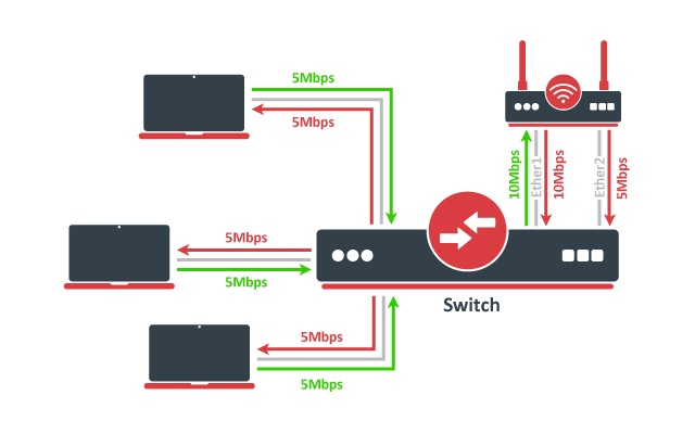
No additional configuration is required for the switch. The image above illustrates how balance-tlb mode works. As you can see the router can communicate to all the clients connected to the switch with a total bandwidth of both links (15Mbps). But as you already know, balance-tlb is not balancing incoming traffic. In our example, clients can communicate to the router with a total bandwidth of the primary link which is 10Mbps in our configuration.
balance-alb
The mode is basically the same as balance-tlb but incoming IPv4 traffic is also balanced. The receive load balancing is achieved by ARP negotiation. The bonding driver intercepts locally generated ARP messages on their way out and overwrites the source hardware address with the unique address of one of the slaves in the bond such that different peers use different hardware addresses. Only MII link monitoring is supported (ARP link monitoring is ignored when configured). The additional downside of this mode is that it requires device driver capability to change MAC address. The mode is not compatible with the local-proxy-arp setting.
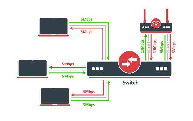
The image above illustrates how balance-alb mode works. Compared to balance-tlb mode, traffic from clients can also use the secondary link to communicate with the router.
Bonding monitoring
Since RouterOS version 6.48, it is possible to monitor the bonding interface and bonding ports. For the 802.3ad bonding mode, more detailed monitoring options are available.
/interface/bonding/monitor [find]
                      mode: 802.3ad           active-backup
              active-ports: ether4            ether6
                            ether5
            inactive-ports:                   ether7
            lacp-system-id: CC:2D:E0:11:22:33
      lacp-system-priority: 65535
    lacp-partner-system-id: B8:69:F4:44:55:66
| Property | Description |
|---|---|
| mode (802.3ad | active-backup | balance-alb | balance-rr | balance-tlb | balance-xor | broadcast) | Used bonding mode |
| active-ports (interface) | Shows the active bonding ports |
| inactive-ports(interface) | Shows the inactive bonding ports (e.g. a disabled or backup interface) |
| lacp-system-id (MAC address) | Shows the local LACP system ID |
| lacp-system-priority (integer) | Shows the local LACP priority |
| lacp-partner-system-id (MAC address) | Shows the partner LACP system ID |
To monitor individual bonding ports, use a monitor-slaves command.
/interface/bonding/monitor-slaves bond1
Flags: A - active, P - partner
 AP port=ether4 key=17 flags="A-GSCD--" partner-sys-id=D4:CA:6D:12:06:65 partner-sys-priority=65535 partner-key=9 partner-flags="A-GSCD--"

 AP port=ether5 key=17 flags="A-GSCD--" partner-sys-id=D4:CA:6D:12:06:65 partner-sys-priority=65535 partner-key=9 partner-flags="A-GSCD--"
| Property | Description |
|---|---|
| port (interface) | Used bonding port |
| key (integer) | Shows the local LACP aggregation key. The lower 6 bits are automatically assigned based on individual port link speed and duplex. The upper 10 bits can be manually specified using the lacp-user-key setting (available only since RouterOS v7.3). |
| flags (string) | Shows the local LACP flags: A - activity (link is active, otherwise passive) T - timeout (link is using short 1-second timeout, otherwise using 30-second timeout) G - aggregation (link can be aggregatable) S - synchronization (link is synchronized) C - collecting (link is able to collect incoming frames) D - distributing (link is able to distribute outgoing frames) F - defaulted (link is using defaulted partner information, indicating that no LACPDU has been received from the partner) E - expired (link has expired state) |
| partner-sys-id (MAC address) | Shows the partner LACP system ID |
| partner-sys-priority (integer) | Shows the partner LACP priority |
| partner-key (integer) | Shows the partner LACP aggregation key |
| partner-flags (string) | Shows the partner LACP flags |
Property Description
This section describes the available bonding settings.
| Property | Description |
|---|---|
| arp (disabled | enabled | proxy-arp | reply-only; Default: enabled) | Address Resolution Protocol for the interface.
|
| arp-interval (time; Default: 00:00:00.100) | Time in milliseconds defines how often to monitor ARP requests |
| arp-ip-targets (IP address; Default: ) | IP target address which will be monitored if link-monitoring is set to arp. You can specify multiple IP addresses, separated by a comma |
| comment (string; Default: ) | Short description of the interface |
| disabled (yes | no; Default: no) | Changes whether the bonding interface is disabled |
| down-delay (time; Default: 00:00:00) | If a link failure has been detected, the bonding interface is disabled for a down-delay time. The value should be a multiple of mii-interval, otherwise, it will be rounded down to the nearest value. This property only has an effect when link-monitoring is set to mii. |
| forced-mac-address (MAC address; Default: none) | By default, the bonding interface will use the MAC address of the first selected slave interface. This property allows to configure static MAC address for the bond interface (all zeros, broadcast or multicast addresses will not apply). RouterOS will automatically change the MAC address for slave interfaces and it will be visible in /interface/ethernet configuration export |
| lacp-mode (active | passive; Default: active) | Specifies whether ports actively or passively participates in the LACP:
|
| lacp-rate (1sec | 30secs; Default: 30secs) | Link Aggregation Control Protocol rate specifies how often to exchange with LACPDUs between bonding peers. Used to determine whether a link is up or other changes have occurred in the network. LACP tries to adapt to these changes providing failover. |
| lacp-user-key(integer: 0..1023; Default: 0) | Specifies the upper 10 bits of the port key. The lower 6 bits are automatically assigned based on individual port link speed and duplex. The setting is available only since RouterOS v7.3. |
| link-monitoring (arp | mii | none; Default: mii) | Method to use for monitoring the link (whether it is up or down)
Warning: Some bonding modes require specific link monitoring to work properly. |
| min-links (integer: 0..4294967295; Default: 0) | How many active slave links needed for bonding to become active |
| mii-interval (time; Default: 00:00:00.100) | How often to monitor the link for failures (the parameter used only if link-monitoring is mii) |
| mlag-id (*integer: 0..4294967295;*Default:) | Changes MLAG ID for bonding interface. The same MLAG ID should be used on both peer devices to successfully create a single MLAG. See more details on MLAG. |
| mode (802.3ad | active-backup | balance-alb | balance-rr | balance-tlb | balance-xor | broadcast; Default: balance-rr) | Specifies one of the bonding policies
Important: MikroTik devices with Marvell Prestera switch and 88E6393X, 88E6191X, 88E6190 switch chips support bridge hardware offloading with bonding interfaces. Only 802.3ad (LACP), balance-xor (static LAG) and active-backup bonding modes are hardware offloaded, other bonding modes will use the CPU's resources. |
| mtu (integer; Default: 1500) | Maximum Transmit Unit in bytes. Must be smaller or equal to the smallest L2MTU value of a bonding slave. L2MTU of a bonding interface is determined by the lowest L2MTU value among its slave interfaces |
| name (string; Default: ) | Name of the bonding interface |
| primary (string; Default: none) | Controls the primary interface between active slave ports, works only for active-backup, balance-tlb and balance-alb modes. For active-backup mode, it controls which running interface is supposed to send and receive the traffic. For balance-tlb mode, it controls which running interface is supposed to receive all the traffic, but for balance-alb mode, it controls which interface is supposed to receive the unbalanced traffic (the non-IPv4 traffic). When none of the interfaces are selected as primary, device will automatically select the interface that is configured as the first one. |
| slaves (string; Default: none) | At least two ethernet-like interfaces separated by a comma, which will be used for bonding |
| up-delay (time; Default: 00:00:00) | If a link has been brought up, the bonding interface is disabled for up-delay time and after this time it is enabled. The value should be a multiple of mii-interval, otherwise, it will be rounded down to the nearest value. This property only has an effect when link-monitoring is set to mii. |
| transmit-hash-policy (encap-2-and-3 | encap-3-and-4 | layer-2 | layer-2-and-3 | layer-3-and-4; Default: layer-2) | Selects the transmit hash policy to use for slave selection in balance-xor and 802.3ad modes
Important: MikroTik devices with Marvell Prestera switch will always use Layer2+Layer3+Layer4 for a transmit hash policy, while 88E6393X, 88E6191X, 88E6190 switch chips are limited to Layer2 transmit hash. Changing the transmit hash policy manually while HW offloading is used will have no effect. |